Product Description
We have many orders for vacuum tables, expect 9-16 days delivery time. Please note that the vacuum tables we manufacture are black and not white as in the video.
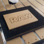
RawVac™ Vacuum Tables
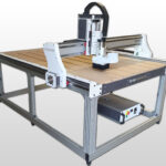
RawVac™ is a modular vacuum workholding system developed for fast, safe, and flexible clamping on CNC machines — without traditional clamps or screw fixtures. The tables are available in 300×300 mm and 600×500 mm, and are designed to be placed directly on top of an existing machine bed. This makes RawVac ideal for both prototyping and production.
A well-designed channel and hole pattern helps distribute vacuum evenly across the surface, resulting in more predictable workholding — even for small parts, mixed part sizes, or irregular shapes.
RawVac™ vacuum tables are made from a high-performance, elastomer-based material with industrial-grade wear resistance. The result is a tight, robust, and chemical-resistant surface with a professional finish.


Modular System with Zone Control
RawVac is built to scale and expand over time. Multiple vacuum tables can be connected in parallel and controlled through a manual control unit (manifold) with taps/valves, so you can distribute vacuum intelligently between tables or zones depending on the job you’re running.
That means you can run a single table when you want maximum holding force on a smaller part, or open additional outlets when you need to cover larger areas and run multiple workstations at the same time. With zone control, you can also shut off unused areas and concentrate suction where the material actually sits, giving a more stable hold and better use of the pump’s capacity.
In short: you can start with a simple base setup and expand into a complete system as demands grow—without having to change platforms.

Zone Division and Flexible Vacuum Control
Each RawVac table is divided into multiple vacuum zones so the active vacuum area can be matched to the workpiece. Zones that aren’t being used can be sealed off with the included rubber plugs, concentrating the vacuum exactly where it’s needed.
For extra flexibility, sealing strip is also included. With it, you can create your own custom zones directly on the table surface, which is practical for unusual contours or when you want to make repeatable “templates” for production runs. This is especially useful for small workpieces, irregular shapes, fixture work and contour milling, and batch production with recurring geometries.
The zone system improves efficiency by reducing unnecessary airflow and leakage.

Through-Cutting with Spoilboard (MDF)
RawVac is designed to work for through-cutting when paired with an MDF spoilboard. MDF is porous and lets air pass in a controlled way, which allows the vacuum to “pull through” the sheet and create an even low pressure beneath the workpiece.
When the pump lowers the pressure under the material, atmospheric pressure from above pushes the workpiece down against the spoilboard—and that’s the force that provides stable hold-down across the entire surface.
In practice, this means you can mill with more confidence and less setup, since the workpiece is held in place without mechanical clamps. It also lets you use the spoilboard as a protective layer, so you can cut through the material and into the spoilboard without risking damage to the vacuum table itself.
RawVac™ Gasket
Used on top of the spoilboard to provide better sealing and a more “forgiving” hold-down. By reducing leakage and smoothing out vacuum distribution, you get a more stable grip—especially when running small parts, when the workpiece doesn’t cover the entire zone, or when the spoilboard condition varies across the surface. The spoilboard is easy to resurface and replace when it gets worn, while the gasket sheet is a consumable that’s replaced as needed. With the right machine settings, the same gasket sheet can also last a long time, even with repeated through-cutting. See our RawVac Gasket product for more information.

This is Included
- RawVac vacuum table in the selected size
- 10mm Hose + fittings (push-to-connect) for vacuum pump connection
- Sealing strip for flexible zone division
- Rubber plugs for sealing zones
If you have your own pump, you can adapt it to be able to connect a 10mm hose, either with a Push-to-connect connection or a similar solution.
RawVac™ Vacuum Pumps

RawVac 8.5 – Compact and Efficient
Nominal airflow (free air): 8.5 m³/h (≈ 142 L/min)
Ideal for small workpieces and well-sealed fixtures where compact size and low noise matter.

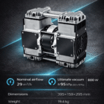
RawVac 29 – For Higher Demands
Nominal airflow (free air): 15 m³/h (≈ 250 L/min)
A strong all-round choice for standard tables, MDF spoilboards, and through-cutting with moderate leakage.

RawVac 29 – For Higher Demands
Nominal airflow (free air): 29 m³/h (≈ 480 L/min)
Best for larger surfaces, multiple zones/tables, and higher leakage situations where extra airflow improves stability.
RawVac Pumps
A vacuum table is only as good as the pump behind it. The right pump capacity provides more stable clamping, better repeatability, and a system that feels easier to use — especially with MDF spoilboards and through-cutting.
RawVac pumps are oil-free and selected specifically for vacuum workholding — meaning stable negative pressure in a system where some airflow and leakage can be present (for example with spoilboards and through-cutting).
This is not the same type of pump commonly used for things like heat pump installation, where oil-lubricated service pumps are typically used to evacuate refrigeration systems. They are built for a different application and operate under different conditions.
Read more about our pumps here: RawVac™ Vacuum Pumps
10 mm (≈3/8”) connections – built for higher flow
Others who manufacture vacuum tables use a 5/16” OD x 1/8” NPT push-to-connect fitting, where 5/16” equals 7.94 mm (≈ 8 mm) outer diameter. We use 10 mm hose instead, which is roughly 3/8” (≈ 9.53 mm).
It may look like a small difference, but in a vacuum system hose size directly affects airflow and pressure drop. Geometrically, 10 mm provides about 56% more cross-sectional area than ~8 mm, which allows significantly higher airflow with less restriction. In practice this means faster recovery when you place a sheet on the table, a more stable vacuum level under small leaks, and better margin during through-cutting or when holding smaller parts.
The larger hose is also more robust in everyday use, helping reduce the risk of micro-leaks and improving long-term reliability.
How Vacuum Workholding Works
A vacuum table does not hold the workpiece by “suction” in the traditional sense. Instead, negative pressure is created between the table and the workpiece by removing air using a vacuum pump. As the pressure under the workpiece is reduced, atmospheric pressure above presses the material down against the table/spoilboard.
In real CNC machining, performance is largely determined by leakage. Small leaks in porous materials, edges, zones, or fittings can quickly reduce vacuum level and stability. That’s why channel structure, surface finish, zone control, and sealing strategy are critical.
Reference: Gauge Pressure vs Absolute Pressure
Vacuum level is commonly expressed in two ways:
- Gauge pressure: 0 bar = atmospheric pressure, negative values indicate underpressure
- Absolute pressure: 0 bar abs = perfect vacuum, 1.013 bar abs ≈ atmospheric pressure at sea level
This means:
- −1.0 bar (gauge) is the theoretical limit, corresponding to 0 bar abs (perfect vacuum)
- −0.95 bar (gauge) typically corresponds to about 0.05–0.06 bar abs (≈ 50–60 mbar abs), depending on local atmospheric pressure
Typical Measured Vacuum (Reference)
In a well-sealed setup (good sealing, minimal leakage), it is normal to see high values on the vacuum gauge. In our own sealed test setup we typically measure around −0.95 to −0.97 bar.
Actual results depend on material, spoilboard condition, leakage, and pump choice.
Theoretical Holding Force (Transparent Calculation)
Maximum theoretical holding force is determined by pressure difference and area:
Holding force (N) = ΔP (Pa) × Area (m²)
Example reference: at −0.95 bar (≈ 95 kPa pressure difference) and a fully sealed surface, theoretical maximum force is approximately:
- 300×300 mm (0.09 m²): ~0.87 ton equivalent
- 600×500 mm (0.318 m²): ~3.1 ton equivalent
Important: these values are theoretical maxima based on pressure differential and full sealing across the entire surface. Real holding force depends on sealing, material porosity, spoilboard condition, leakage, and pump capacity.
The product is CE-marked and developed in accordance with applicable EU requirements for safe and proper use in professional environments.