
How to cut with good results
If it’s the first time you cut with a CNC machine, you can read the text below to get started.
Regardless of whether you built or purchased your machine, you need software to run it. The work flow looks like this.
Draw your part in, for example, CorelDRAW, fusion 360 or Google Sketchup. You can choose which software you like as long as you can save the file in .DXF format for 2-2.5D or .STL for 3D cutting. A good free software is Inkscape.
With your .DXF or .STL file, you need to prepare it with a CAM software. A CAM software gives instructions to the machine how to cut your part. With the CAM software you will set the type of end mill, end mill diameter, depth, thickness of material to be cut, etc. An experienced user will use CAM software’s like Vcarve Pro or Fusion 360, but if you are new to all this and don’t know what to use, I recommend a very simple software called Estlcam (www.estlcam.com). With Estlcam you can cut both 2D and 3D. Estlcam is very cheap (around 50Eur) and a perfect software to start with.
After you have prepared your file in a CAM software you can send it to the machine software (Mach3 or Eslcam if you use Arduino)
This is what it takes to cut your part. It may seem difficult at first but after doing it 1-2 times, it is easy.
If you are new to all this you can follow the guides below.
If you have Arduino as electronics:
- Download a 2-3D drawing software, any software will do aslong as you can save your file in .DXF format. An example is Google Sketchup, which is free.
- Download Estlcam from estlcam.com which is free for 30 days after it costs around 50Eur, compared with eg Vcarve pro that can cost around 800Eur. Estlcam does the job as well and can also cut in 3D which is unique.
- For Arduino this is what is required and you can read further below on how to cut with the machine
If you have Drivers as Electronics
- Download a 2-3D drawing software, any software will do aslong as you can save your file in .DXF format. An example is Google Sketchup, which is free.
- Download a CAM software like Vcarve or Estlcam from estlcam.com which is free for 30 days after it costs around 50Eur, compared with eg Vcarve pro that can cost around 800Eur. Estlcam does the job as well and can also cut in 3D which is uniq
- Download Mach3 demo or purchase program (cost about 200EUR) http://rawcnc.com/product/mach3-cnc-software/
With driver electronics, you need to have a control software like Mach3. The advantage of drivers is that you can choose which software you want and can grow with the machine. Arduino electronics are much more limited.
Cutting with your machine
If you have Arduino as electronics, it’s pretty straightforward, draw your part, save it in .DXF format and set up the tools as shown below and then cut your part.
With driver electronics and Estlcam, you need to set up Estlcam to work with Mach3. Estlcam is actually a software for Arduino but works with Mach3. Start with Estlcam and then advance up to more expensive CAM programs such as Vcarve that I use. Follow the wizard below if you have Drivers and Estlcam. We need to tell Estlcam to save our files in a format that can be read by Mach3 or UCCNC.
Start Estlcam and go to the “Setup / Basic setup” menu. In the drop-down menu to the right, select Mach 3 / Mach 4 (or UCCNC) then press OK.
 Go to the menu “Setup / CNC Programs” Select Mach3 / Mach 4 also here
Now Estlcma is set to print instructions to Mach3 or UCCNC. If you create a file and set up the tools according to the guide below and then save the file by going to “File / Save CNC program”. You now have a file that can be read by another software such as Mach3 or UCCNC.

This file is now in .TAP format that can be loaded into Mach3
To cut with successful results
It takes a while before learning how to cut various materials, it is a balance of speed, depth and cutting tools.
You can watch this video to see an example on how I work http://rawcnc.com/cutting-parts-from-start-to-finish/
In all CAM softwares, you have a tool list of different tool diameters and types of end mills.
Change or create new tools, you can copy the ones you see below that I use for wood cutting: As you can see I have two different speeds for the same tool. The reason is that I want to cut slower for small parts like holes and faster speeds for larger parts. If you go to fast on small objects the result will be bad.
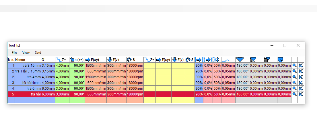
The image above has two settings for each end mill but different speeds
- The first field after “Name” is the diameter of the end mill, e.g. 4mm.
- Z + is how deep we want to cut per turn in our case 4mm which is enough, larger end mills like 6 or 8mm should have lower eg 2-4mm deep per turn.
- The next field to change is F (z), which is the speed of the machine. Start at 2000mm / min and slowly increase until you find your speed, the slower you cut the better results (Drivers can handle faster speeds than Arduino).
- F (Z) is how fast the end mill will go down, I usually have a low speed between 300-800mm / min. Begin with 400 and work your way up.
- The field after “S” is spindle speed. You can connect a spindle that has an inverter directly to the PCB to control it but I prefer to have it on the side and set the speed manually but add the speed of the spindle here so you can remember it. I have set it to 18,000 rpm, which is good for wood. Too fast and the end mill burns and too slowly gives a bad result. One rule is that hard materials require lower speed on the spindle.
I usually work with one size of the end mill per project (eg 4mm) to avoid changing end mills during work. Let’s work with a 4mm end mill as an example.
Let’s say I’ll cut out a small piece of 20×20 cm and some smaller holes 4- 12mm. I want to cut the profile with “Wood 4mm (trä 4mm)” and i want to cut the holes with “Wood hole 4mm (trä Hål) “. If you cut small holes too fast it makes the machine go back and forth to fast which can result in oval holes. The Z-axis can weigh up to 10kg depending on the spindle and it is very difficult for a non-steel machine to handle to fast speeds. An industrial machine would do this without any problems. As you can see, there is a lot to think about.
As an example, I’ll cut out a Raw s-70 side plate

Estlcam makes all this incredibly easy, just click on the parts you want to set up. I have marked a hole that I want to cut out. I choose the tool “wooden hole 4mm”. When I select the hole a box with settings will show up.
- Toolpath dept: is how deep i want to cut. My material is 19mm so I choose to go .5mm deeper so I know I’m going through. I also have a piece of wood under my material so I do not cut into the table, for example a Masonite piece of 3mm
- Holding tab length: Means leaving some material to hold the piece you have cut in place. Click on the image “Holding tab” and place your tabs in the red circle.
That’s it, go to Estlcams home page to read more.
If you have another software than Estlcam, it looks similar.
No comments yet.